FAQs
FAQ Subject
Bit error in transmission; check if the link loss is too much,The rolling diameter shall not be too short (not less than 20CM), unstable transmission because of operating the temperature of environment is too high.
Optical transceiver not receiving video signal, need to check the video input.
Network setting for WNAP-7200
WNAP-7200(1)
IP address: 192.168.0.1 username and password is "admin/admin".
MAC: 00:30:4F:7B:5C:8E
WNAP-72000(2)
IP address: 192.168.0.2 username and password is "admin/admin".
MAC: 00:30:4F:7B:5C:B6
1. Please follow the WAP-7200(1) Bridge setting, first.
(1-1.) PC (1) set the Internet Protocol (TCP/IP) Properties as the Fixed IP address 192.168.0.100 and uses RJ-45 to the WNAP-7200(1) LAN port.
Run the command "ping 192.168.0.1" and make sure the WNAP-7200(1) Respond PC (1).


(1-2.) Key the user name and password: "admin/admin".
Get into the WNAP-7200 WEB UI Configuration Tool function.

(1-3.) Please set the WNAP-7200(1) AP Bridge-Point to Point mode in the Basic Setting.
Key the WNAP-7200(2) MAC address to the MAC Address and set the same channel.
Please remember to apply the following WNAP-7200 Bridge setting.
Please refer to the WNAP-7200 Status.

2. WNAP-7200(2) Bridge setting
(2-1.)Please repeat the WNAP-7200(1) Bridge setting.
Only change the WNAP-7200(2) IP address as 192.168.0.2 in the System Utility function to easily manage the WNAP-7200 bridge topology devices.
Please write the note (IP address, user name, and password) on the WNAP-7200 FCC label to remind your device setting.)

(2-2.) When you can get the 192.168.0.1 Respond from the WNAP-7200(2), your WNAP-7200 Bridge mode is finished.

3. When you set the WNAP-7200 AP Bridge-Point to Multi-Point mode , you must pay the attention for the following rules.
(3-1.) Do not set the looping bridge topology.
For example : There are three WNAP-7200 in the bridge topology. If you set the AP1 , AP2 and AP3 MAC address for each other, you will get the looping topology.

You should set the WNAP-7200 Multi-Point topology like the following setting.

WAP-8000 Country Code And RF Power Settings
The country code can be selected here to fit the local restriction law. Changing country code will cause the available channel changes.
**Be notice, when select:
ETSI (1), the RF output power supports options: Full, 1/2, 1/4, 1/8, 1/16
ETSI (2), the RF output power supports options: Full, 1/2, 1/4

WILDCARD :
11b/g: 1.2.3.4.5.6.7.8.9.10.11
11a: 36.40.42.44.48.50.52.56.58.60.64.149
152.153.157.160.161.165
China
11b/g: 1.2.3.4.5.6.7.8.9.10.11.12.13
11a: 149. 153.157.161.165
ETSI(2) :
11b/g: 1.2.3.4.5.6.7.8.9.10.11.12.13
11a: 36.40.44.48.52.56.60.64
ETSI(1) :
11b/g: 1.2.3.4.5.6.7.8.9.10.11.12.13
11a: 36.40.44.48.52.56.60.64.100.104.108.
112.116.120.124.128.132.136.140
Japan:
11b/g: 1.2.3.4.5.6.7.8.9.10.11.12.13.14
11a: 34.38.42.46
US:
11b/g: 1.2.3.4.5.6.7.8.9.10.11
11a: 36.40.42.44.48.50.52.56.58.60.64.149
152.153.157.160.161.165
Please refer to the WAP-8000 TX Power dBm level adjust WEB UI setting:
In the wildcard code , the WAP-8000 default is full level (Max up to 26 dBm /400mWatt).
Please refer to the wireless setting after choosing the country doe ( ETSI(2)/ETSI(1) ).
Equivalent isotropically radiated power (EIRP) in the EU is limited to 20 dBm (100 mW).
Remember when calculating your total output that the FCC only allows 36dBm EIRP (4 watts)!
Please set the WAP-8000 Transmit Power as the 1/4 power level.

ETSI (1)

ETSI (2)
dBm to Watt Conversion Table
dBm | Watts |
| dBm | Watts |
0 | 1.0 mW |
| 16 | 40 mW |
1 | 1.3 mW |
| 17 | 50 mW |
2 | 1.6 mW |
| 18 | 63 mW |
3 | 2.0 mW |
| 19 | 79 mW |
4 | 2.5 mW |
| 20 | 100 mW |
5 | 3.2 mW |
| 21 | 126 mW |
6 | 4 mW |
| 22 | 158 mW |
7 | 5 mW |
| 23 | 200 mW |
8 | 6 mW |
| 24 | 250 mW |
9 | 8 mW |
| 25 | 316 mW |
10 | 10 mW |
| 26 | 398 mW |
11 | 13 mW |
|
|
|
12 | 16 mW |
|
|
|
13 | 20 mW |
|
|
|
14 | 25 mW |
|
|
|
15 | 32 mW |
|
|
|
The case of WNAP-7200 is designed more easy, more convenient and friendly installation. Please refer to below figure for cable installation.
Step1:
Please wind the RJ-45 cable around the pillar for one or two circle to fix cable, prevent loosing from LAN port connector.

Step2:
Please cover the Back Cover.
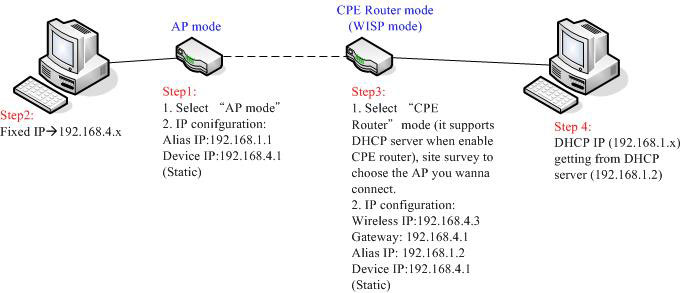
Please follow below figure and steps for CPE Router configuration.
The GT-1205Av2 provides hardware fiber redundancy function via the built-in DIP-switch and can be configured as a 3-port Ethernet switch or 2-port Fiber Redundant media converter. With the 3-port Switch mode, it can operate Store-and-Forward mechanism with high performance. With the 2-port Fiber Redundant mode; it provides redundancy of link for highly critical Ethernet applications. The redundant mode supports auto-recover function. If the destination fiber port of a packet is link down, it will forward the packet to the other fiber port of the backup pair.